Unique technology
Efficient and reliable airborne leak detection
of gas pipelines using CHARM®
How does gas detection work?
CHARM® measures the concentration of methane (the main component of natural gas) in the air and detects any traces of released natural gas. In order to identify traces of natural gas, CHARM® uses the property of chemical compounds to absorb light of certain wavelengths. The Differential Absorption LIDAR (DIAL) method is used for this purpose, whereby the system emits two laser pulses of different wavelengths.
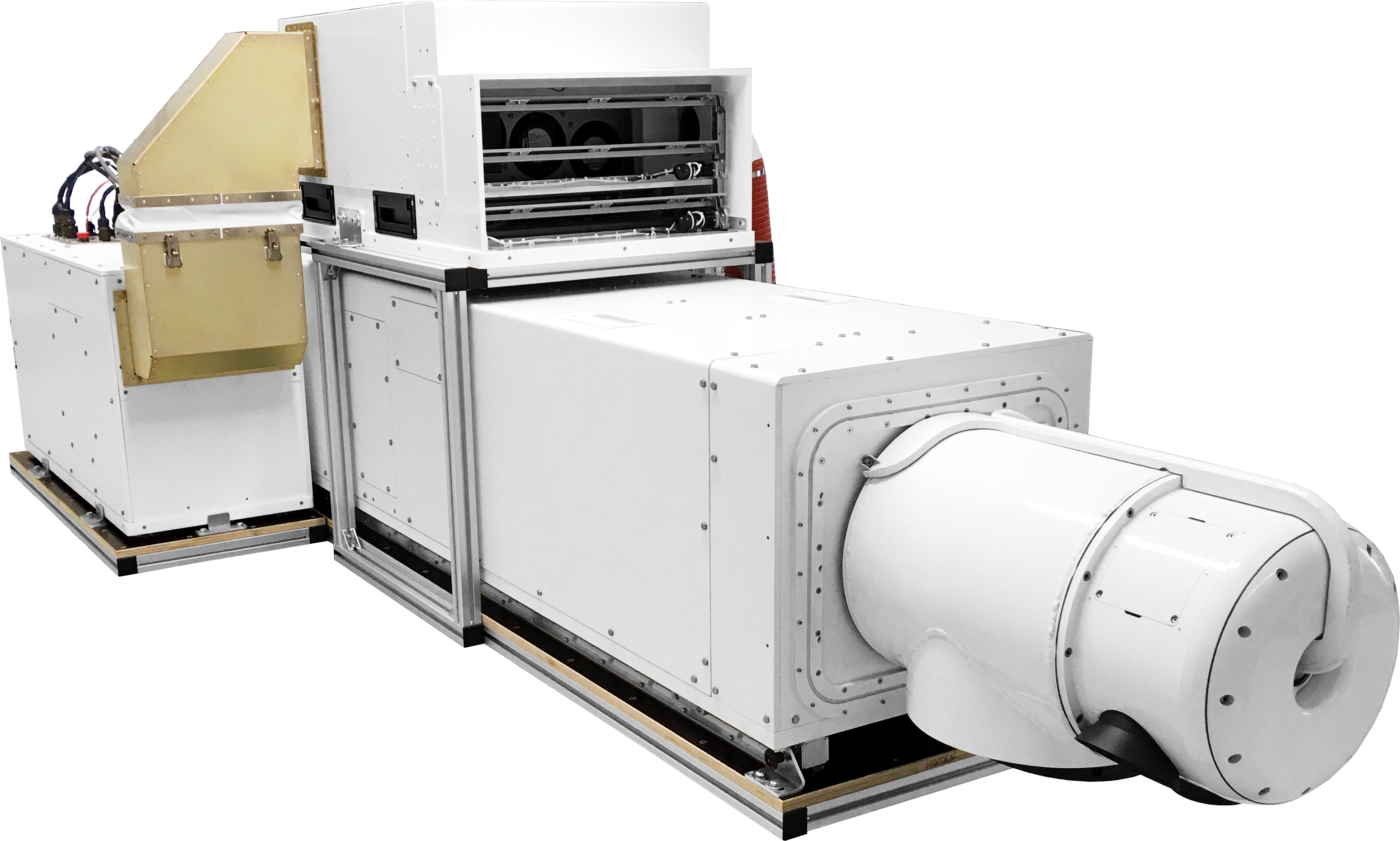
CHARM®
| In use since: | 2008 – 2020 since 2020 |
Aircraft used: | MD 900 Explorer |
| Certified: | since 2008 through the DVGW |
Measurement method: | DIAL |
| Measured medium: | Methan |
| Measurements per second: | 1000 |
Scan sector: | up to 25 m |
| Resolution: | approx. 1-2 measurement/m² |
| Laser beam guidance over pipeline: | automatic |
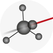
Measuring beam
Light is absorbed by methane
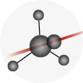
Reference beam
Light is not absorbed by methane
The first wavelength is tuned in such a way that it is specifically absorbed by methane, while the second wavelength is not absorbed. Both light impulses hit the ground and are scattered in all directions. A very small part of the light returns to the system and is detected by an extremely sensitive sensor. The number of methane molecules in the laser path can be determined from the ratio of the light scattered back to the measuring system by both laser pulses. CHARM® performs 1000 measurements per second.
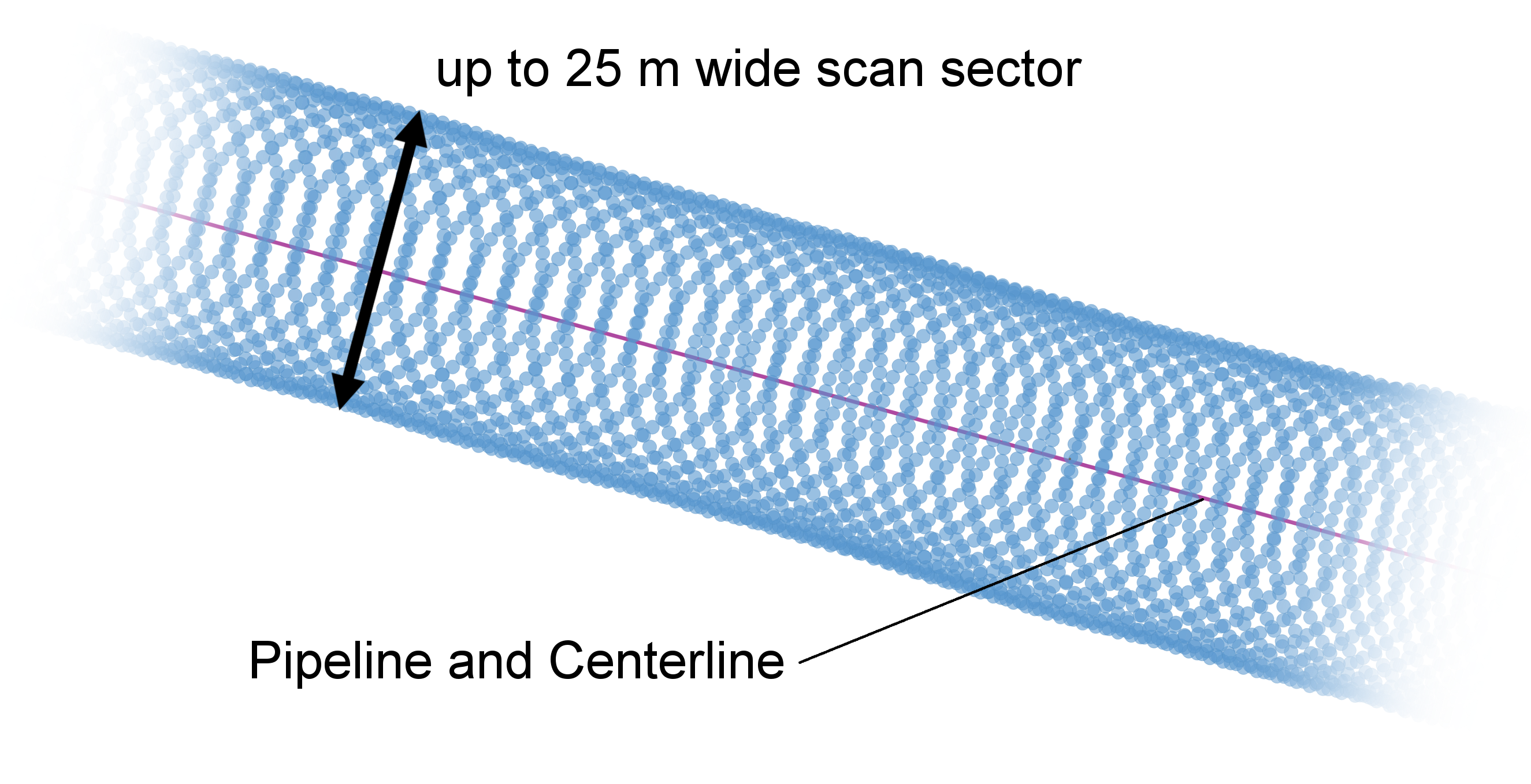
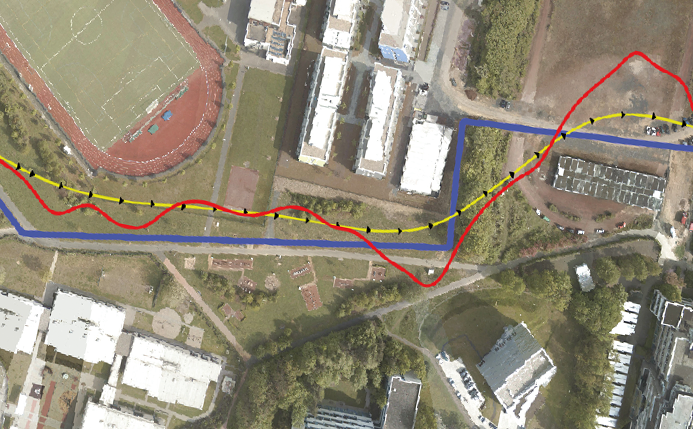
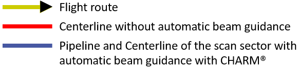
CHARM® generates 1000 measurements per second, which are distributed along the pipeline in up to 25 m wide sector. The center axis of the scan sector is called centerline.
Navigation and automatic beam guidance
In order to determine the exact spatial position of the measuring system, CHARM® is equipped with a DGPS receiver (DGPS: Differential Global Positioning System). To specify the spatial position and movement of the helicopter (yaw, pitch and roll angle, see figure below), an additional inertia measuring unit (IMU) is installed on board. This navigation data is linked with the onboard pipeline database, enabling real-time guidance of the measuring beam to the ground.
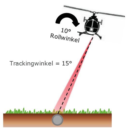
Since a helicopter cannot follow the course of the pipeline with centimeter accuracy, ADLARES GmbH has developed a fully automated technology that guides the measuring beam along the pipeline. The scanning head is movable and can therefore compensate the helicopter’s horizontal deviation of up to 50 m compared to the pipeline. The rotation of the helicopter around its longitudinal axis (roll, see figure below) is also compensated this way. The rotation of the scanner in relation to the vertical axis of the helicopter is called the tracking angle.
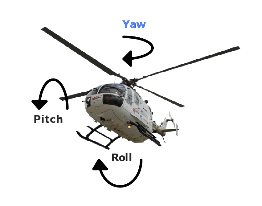
YAW: DRotation around the vertical axis,
Pitch: Rotation around the lateral axis,
Roll: Rotation around the longitudinal axis
With CHARM®, an automated beam guidance system was developed to offset the numerous issues that arise when flying without a movable scanner. Not least because it is always necessary to fly downwind of the pipeline in order to reliably detect escaping gas that is blown away from the exit point. Yet the gas cloud is further diluted with increasing distance to the exit point, with the concentration consequently decreasing. When a pipeline leak is far away from an area of operation, the gas concentration at the exit point is so low that an increase cannot be measured when there is even the slightest spatial measurement deviation from the exit point. (see figure “Beam guidance downwind of pipeline”).
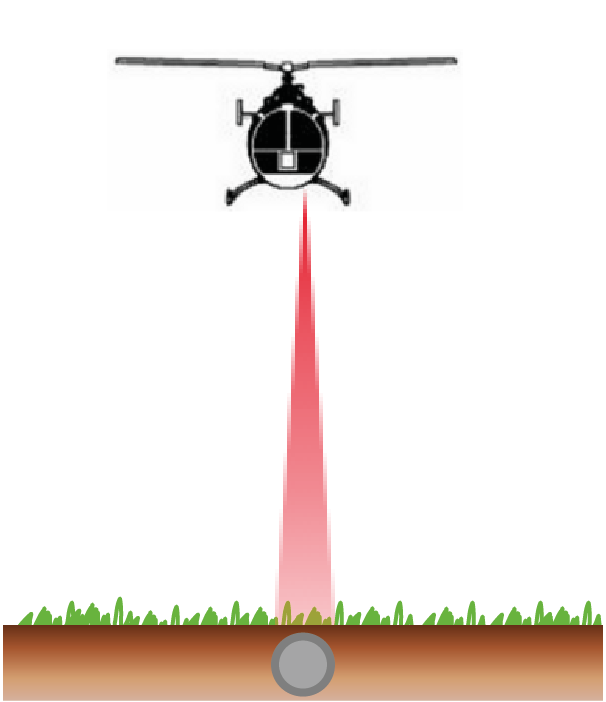
Helicopter vertically above pipeline
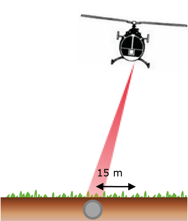
Helicopter with lateral alignment to the pipeline, autotracking keeps the measuring beam over the pipeline
Beam guidance downwind of the pipeline due to the rigid laser beam exit without movable scanner, the measuring beam always measures perpendicularly from the helicopter to the ground
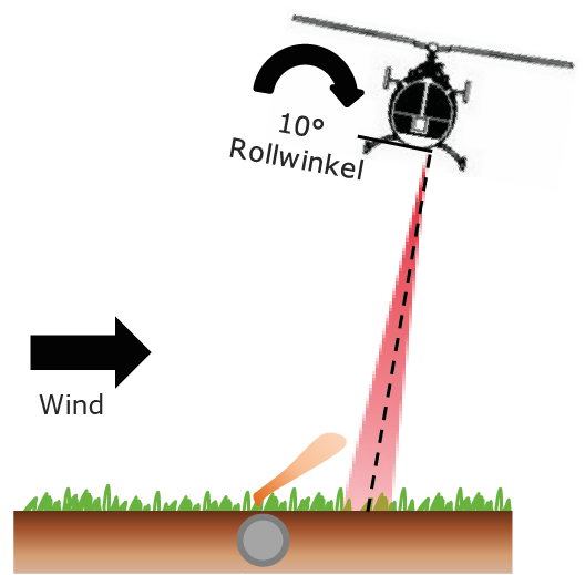
Automatic beam guidance with CHARM®, the movable scanner compensates the roll angle and the distance to the pipeline
A 20° wind variability is normal even with a relatively constant wind direction. This creates another problem, where locating the emission point becomes mere speculation. A 20° deviation of the real wind from the apparent wind can, depending on the distance to the pipeline, lead to a significant misalignment of more than 50 m between the assumed exit point and the actual emission point (see figure on the right).
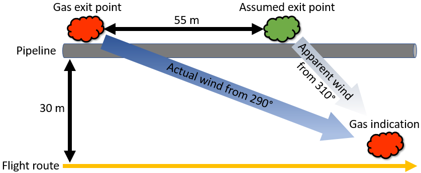
Relationship between the gas exit point and the gas indication if the wind direction is assumed incorrectly
Even if the pilot manages to consistently fly on the downwind side of the pipeline, without a movable scanning head there is no guarantee that measurements are taken on the correct side of the pipeline. This becomes an issue with pipeline bends – for which the helicopter has to take a turn – as that usually leads to rolling movements of the aircraft about its longitudinal axis. The measuring beam without a movable scanning head is shifted laterally depending on the flight altitude and can thus be directed via the pipeline to the windward side. If gas then escapes from the pipeline, the system can no longer detect it (see figure on the left).