Gas pipelines are not all built the same way, and that distinction matters more than most people outside the energy industry realize. Whether you are a grid operator planning your next inspection campaign, an engineer reviewing compliance requirements, or simply someone trying to understand how natural gas reaches your home, knowing the difference between transmission and distribution pipelines is the starting point for everything else. The type of pipeline determines its operating pressure, its construction, who regulates it, and, critically, how it should be inspected for leaks.
What is a gas transmission pipeline?
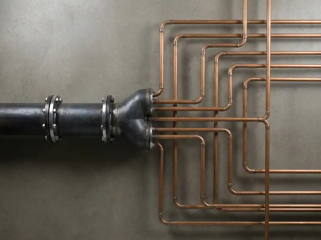
A gas transmission pipeline is a high-pressure conduit that moves large volumes of natural gas over long distances, typically from production sites, import terminals, or storage facilities to regional distribution networks or large industrial consumers. These pipelines operate at pressures that can exceed 70 bar and are usually made from high-grade steel, buried underground across rural and semi-rural corridors.
Transmission pipelines form the backbone of a country’s gas infrastructure. In Europe, they are operated by Transmission System Operators (TSOs), who are responsible for maintaining the integrity of these assets and ensuring continuous supply. Because of the high pressures involved, even a small defect in a transmission pipeline carries a meaningful safety and environmental risk. The physical properties of steel pipes at pressures above 5 bar mean that the smallest possible leak rate is approximately 150 litres per hour, a figure that sets the baseline for any serious inspection standard.
What is a gas distribution pipeline?
A gas distribution pipeline operates at much lower pressures, typically below 16 bar, and is designed to deliver gas from regional offtake points to end consumers, including homes, businesses, and smaller industrial facilities. Distribution networks are denser and more complex than transmission systems, often running beneath city streets and suburban areas.
These pipelines are managed by Distribution System Operators (DSOs) and include a wide variety of pipe materials, from modern polyethylene to older cast iron or steel. Because distribution pipelines are embedded in urban environments, inspection methods need to account for the density of surrounding infrastructure, road surfaces, and the presence of other underground utilities. The lower operating pressures also mean that leak characteristics differ from those found on high-pressure transmission lines.
What’s the difference between transmission and distribution pipelines?
The differences between transmission and distribution pipelines span several dimensions that directly affect how they are built, operated, and inspected.
- Operating pressure: Transmission pipelines run at high pressure, often above 16 bar and sometimes exceeding 70 bar. Distribution pipelines operate at medium to low pressure, generally below 16 bar.
- Pipeline material: Transmission lines are almost always constructed from steel. Distribution networks use a broader mix of materials, including polyethylene, which is now the standard for new installations.
- Geography: Transmission corridors are typically long, rural, and relatively straight. Distribution networks are dense, urban, and branch extensively.
- Operator type: Transmission is managed by TSOs; distribution is managed by DSOs. Each operates under different regulatory frameworks and maintenance obligations.
- Leak characteristics: High-pressure transmission leaks tend to produce more concentrated emissions. Distribution leaks at lower pressures may be smaller and more diffuse, requiring different detection sensitivity.
Understanding these distinctions is not just an academic exercise. It has direct implications for which inspection technologies are appropriate, what detection thresholds are meaningful, and how frequently surveys must be carried out.
Why does pipeline type affect leak detection methods?
The type of pipeline determines the physical characteristics of any potential leak, and those characteristics define what a detection technology needs to be capable of. On high-pressure steel transmission pipelines, the minimum physically possible leak rate is approximately 150 litres per hour. This is not a regulatory choice but a material and pressure constraint: defects in steel pipe at pressures above 5 bar cannot produce smaller emissions than this threshold. Any technology claiming to detect signals below this level on transmission infrastructure is responding to noise, not real leaks.
On distribution pipelines at lower pressures, leak rates can be much smaller, and the detection approach shifts accordingly. Ground-based or vehicle-mounted instruments that operate in close proximity to the pipe trace are well suited to the dense urban environment where distribution networks run. These tools can achieve very close-range sensitivity that is simply not physically meaningful when applied at altitude over a wide corridor.
Another factor is the geometry of underground emissions. Research from METEC and the Engler-Bunte Institute shows that gas escaping from a buried pipeline does not emerge directly above the leak point. Soil structure causes the plume to widen as it travels upward, meaning it can surface several metres away from the actual defect. For reliable detection, a survey must cover a grid extending at least 10 metres either side of the pipeline centerline, with spatial resolution better than 2 metres. A single string of measurement points along the pipe trace is not sufficient to catch real leaks consistently.
For airborne pipeline inspection services, this means the survey must function as a true area scan rather than a line scan, covering the full corridor where a plume might surface rather than just the pipe route itself.
How are gas transmission pipelines inspected for leaks?
Gas transmission pipelines are inspected using a range of methods, but for long rural corridors, aerial survey is the most practical and cost-effective approach. Helicopter-based systems can cover hundreds of kilometres in a single day at speeds that ground teams simply cannot match, making them the preferred tool for large-scale screening of transmission infrastructure.
Effective aerial inspection of transmission pipelines requires technology that can detect the minimum physically possible leak rate under realistic field conditions. This means operating at altitude while maintaining enough sensitivity to identify a 150 litre per hour emission through soil and at wind speeds that reflect typical survey conditions. The detection must also cover a wide enough swath to account for plume drift, rather than scanning only the pipe centerline.
Survey results are most useful when they are delivered in a format that allows operators to act quickly. Web-based GIS platforms that show geo-referenced gas indications on a map, accessible on desktop and mobile devices, allow field teams to verify findings efficiently without waiting for a paper report.
What regulations apply to gas pipeline leak detection in Europe?
European gas pipeline operators are subject to a growing body of regulation aimed at reducing methane emissions from gas infrastructure. The EU Methane Regulation (EU 2024/1787) is the primary framework, and it introduces a structured approach to leak detection and repair (LDAR) that applies across both transmission and distribution networks.
The regulation distinguishes two inspection classes with different sensitivity requirements and monitoring intervals:
- Type-1 inspections require a detection limit of 17 g/h or 7,000 ppm. This level is achievable with Optical Gas Imaging cameras and standard handheld instruments used at close range.
- Type-2 inspections require a much more sensitive detection limit of 5 g/h or 1,000 ppm. This threshold demands more sophisticated equipment. In exchange for meeting this higher standard, operators benefit from a longer inspection interval: underground pipelines inspected to the Type-2 standard need to be surveyed only once every three years rather than more frequently.
Beyond the EU Methane Regulation, the DVGW G465-4-5 standard (formerly known as G501) sets the world’s only technical standard specifically for aerial inspection of underground gas pipelines. Issued by the German Technical and Scientific Association for Gas and Water, it requires reliable detection of 150 litre per hour leaks with an 80% detection probability across five flyovers, within binding operational limits for altitude, airspeed, and wind speed. Certification under this standard is not based on ideal laboratory conditions but on performance within a defined operational envelope, which gives operators a meaningful and reproducible benchmark for comparing inspection technologies.
One important nuance in interpreting these thresholds is the difference between expressing detection capability in grams per hour versus parts per million. Surface concentration in ppm varies with wind speed, atmospheric stability, soil permeability, and ground cover. The same underground leak can produce very different ppm readings depending on conditions outside the operator’s control. An emission rate measured in g/h under controlled test conditions is the only reproducible, technology-neutral metric for certification purposes, which is why the DVGW standard is built around this approach.
How ADLARES Helps You Inspect Gas Transmission and Distribution Pipelines
We offer a complete airborne methane leak detection service built specifically for the demands of gas pipeline inspection. Our CHARM® technology is the world’s only DVGW G465-4-5 certified aerial gas detection system, and it is certified as Type-2 compliant under the EU Methane Regulation, meaning it meets the 5 g/h detection threshold that qualifies underground pipelines for the three-year inspection interval. Here is what sets our service apart:
- True area coverage: CHARM® scans a corridor extending well beyond the pipe centerline, capturing plumes that have drifted laterally through soil before reaching the surface.
- Verified sensitivity headroom: DVGW testing confirmed that CHARM® reliably detects emissions producing 300 ppm in a 2×2 metre area at the surface, three times more sensitive than the 1,000 ppm Type-2 threshold, ensuring reliable detection under all allowable field conditions.
- Full-service quality assurance: Every kilometre of pipeline is reviewed by our operations and data teams. Sections that do not meet the DVGW G465-4-5 operational criteria are re-flown until cleared. Non-relevant findings from nearby biogas or wastewater facilities are filtered out of the final report.
- Secure Web GIS delivery: Survey results are delivered through a secure online platform accessible on desktop and mobile, so your field teams can act on findings immediately.
- Proven at scale: We have inspected over 250,000 kilometres of gas pipeline across Europe for TSOs and DSOs since CHARM® entered commercial service in 2008.
Whether you operate a long-distance transmission corridor or a regional distribution network, we can help you meet your regulatory obligations efficiently and with full methodological transparency. Get in touch with the ADLARES team to discuss your next inspection campaign and find out how our airborne service can fit your pipeline portfolio.