
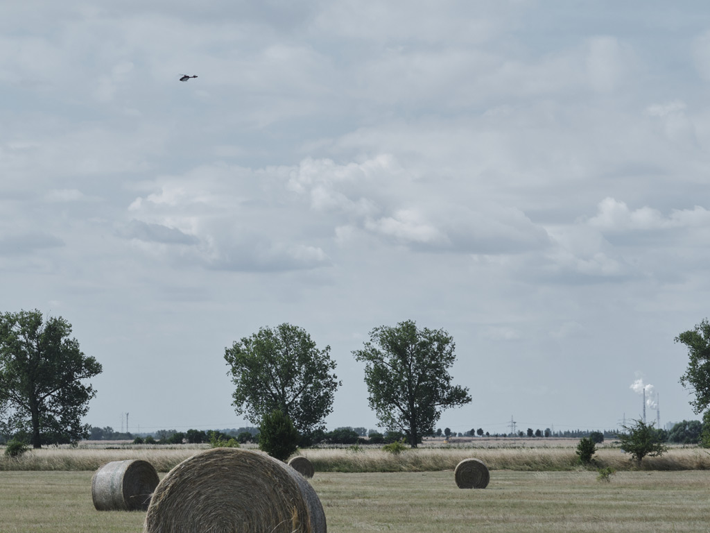
Fugitive methane emissions are one of the most significant and often overlooked contributors to greenhouse gas inventories at gas infrastructure facilities. Unlike combustion emissions, which come from a defined stack or exhaust point, fugitive emissions escape unintentionally from seals, valves, flanges, connectors, and other components throughout a facility. Quantifying them accurately is no longer optional. Under the EU Methane Regulation, operators of compressor stations, metering stations, and storage facilities are required to measure and report emissions at source level, moving away from generic emission factors toward direct measurement. This article walks through the main approaches to quantifying fugitive methane emissions from a facility, from traditional ground-based methods to modern airborne remote sensing.
What are fugitive methane emissions and why do they matter?
Fugitive methane emissions are unintended releases of methane gas from equipment, infrastructure, or processes that are not associated with deliberate venting or combustion. At gas infrastructure facilities, the most common sources include compressor seals, pressure relief valves, flanges, metering equipment, and pipeline connections. Because methane is a potent greenhouse gas with a global warming potential many times higher than carbon dioxide over a 20-year period, even relatively small leaks at a facility can contribute meaningfully to a site’s overall climate impact.
From a regulatory standpoint, the EU Methane Regulation has made quantifying these emissions a legal obligation for Transmission System Operators (TSOs) and other gas infrastructure operators. The regulation requires source-level reporting, meaning operators must identify and measure emissions at individual components rather than applying aggregate estimates across an entire network. This shift toward direct measurement is the foundation for achieving OGMP 2.0 Level 5 compliance, which all EU assets must reach by August 2028. Beyond compliance, accurate quantification helps operators prioritise repairs, reduce gas losses, and demonstrate credible emissions performance to regulators and stakeholders.
How are fugitive methane emissions traditionally measured at a facility?
Traditional approaches to measuring fugitive methane emissions at a facility rely on ground-based, component-level inspection. The most widely used method is the Leak Detection and Repair (LDAR) programme, in which trained technicians walk the facility with handheld instruments such as Flame Ionisation Detectors (FIDs) or optical gas imaging cameras, checking each component individually for signs of leakage.
While these methods are well-established and can be highly accurate at the component level, they have practical limitations at the facility scale. A large compressor station may contain thousands of individual components, making a comprehensive manual survey time-consuming and expensive. Ground-based surveys also struggle to capture total site emissions in a single measurement, which means operators often cannot easily reconcile their bottom-up component inventory with a top-down total figure. This reconciliation step is precisely what the OGMP 2.0 Level 5 framework requires, and it is where traditional methods alone fall short.
Some operators supplement manual surveys with tracer gas dilution techniques or downwind plume sampling to estimate total site flux. These approaches can provide a site-level total but require specific meteorological conditions and careful experimental setup to produce reliable results. They are also typically conducted as separate exercises from the component-level survey, adding cost and logistical complexity.
What is the DIAL method and how does it detect methane remotely?
Differential Absorption LIDAR, commonly known as DIAL, is a laser-based remote sensing technique that detects and measures the concentration of specific gases in the atmosphere without requiring physical contact with the source. The principle relies on the property of chemical compounds to absorb light at characteristic wavelengths. Methane, like all molecular gases, absorbs infrared light at specific frequencies that are unique to its molecular structure.
In a DIAL system, two laser pulses are emitted simultaneously at slightly different wavelengths. One pulse is tuned to a wavelength that methane absorbs strongly; the other is tuned to a nearby reference wavelength where methane absorption is minimal. By comparing the intensity of the returning light at both wavelengths, the system can calculate the concentration of methane along the laser path with high precision. The difference in absorption between the two wavelengths is directly proportional to the amount of methane present, allowing the system to distinguish genuine methane signals from background noise or other atmospheric effects.
Because DIAL operates from a distance and measures along a line of sight rather than at a single point, it is well suited to scanning large areas quickly. When integrated into an airborne platform, a DIAL system can cover extensive ground while building up a spatially resolved map of methane concentrations below the flight path. This makes it fundamentally different from a single-point sensor and gives it the ability to detect and characterise emission sources across an entire facility or pipeline corridor in a single pass. Airborne methane inspection services using DIAL technology have become an increasingly important tool for operators seeking efficient, high-coverage emission surveys.
How does airborne methane quantification work over a facility?
Airborne methane quantification over a facility combines the concentration mapping capability of a remote sensing instrument with supplementary wind data to calculate emission flow rates. The process works in two complementary steps that together satisfy the dual measurement requirement under OGMP 2.0 Level 5.
In the first step, the aircraft scans the facility and maps methane concentration across the entire site at asset level, identifying which specific components or areas are emitting. This provides the source-level picture required for bottom-up emission inventories. In the second step, the total methane flux leaving the facility is calculated by combining the measured concentration data with wind speed and direction measurements. Wind data can be collected by ground-based instruments during the survey or sourced from other reliable meteorological data. Multiplying the measured concentration by the wind vector across a defined cross-section of the plume yields an emission flow rate expressed in kilograms per hour.
The key advantage of this approach is that both the source-level map and the total site quantification are produced in a single airborne survey, typically completed in a matter of minutes over a facility. This eliminates the need for separate measurement campaigns and allows operators to directly reconcile their component-level inventory against the independently measured site total. Discrepancies between the two figures highlight unaccounted emission sources or miscalibrated component estimates, which is exactly the kind of quality control that regulators expect under OGMP 2.0 Level 5.
What factors affect the accuracy of airborne methane emission estimates?
Several variables influence the accuracy of airborne methane emission estimates, and understanding them helps operators interpret survey results correctly and set realistic expectations for measurement uncertainty.
- Wind conditions: Wind speed and direction are the most important external variables. Higher wind speeds dilute the methane plume and carry it downwind, affecting both the detected concentration and the calculated flux. Surveys conducted at very low or highly variable wind speeds introduce greater uncertainty into flow rate calculations. Most airborne systems define an operational wind speed envelope within which results meet accuracy requirements.
- Atmospheric stability and turbulence: Vertical mixing in the atmosphere affects how a methane plume disperses. Stable atmospheric conditions allow plumes to remain coherent and concentrated, making them easier to characterise. Turbulent conditions cause rapid mixing and can reduce the measured peak concentration, potentially affecting emission rate estimates.
- Sensor sensitivity and spatial resolution: The ability of the instrument to detect low concentrations reliably, and to resolve the spatial extent of a plume accurately, directly affects whether small emission sources are captured and correctly attributed to specific assets.
- Flight altitude and speed: These parameters determine the measurement footprint and the number of data points collected per unit area. Higher altitude increases coverage but reduces spatial resolution; lower altitude improves resolution but reduces the area scanned per pass.
- Quality of wind data: Since flow rate calculations depend on accurate wind measurements, the precision and representativeness of the wind data used in the calculation are critical factors in the overall accuracy of the emission estimate.
Independent benchmarking studies, such as the GERG Technology Benchmark for Site-Level Methane Emissions Quantification, have tested airborne quantification methods against controlled releases under defined conditions, providing operators with validated performance data rather than manufacturer claims alone.
Which methane quantification method is best for your facility type?
The most appropriate method depends on the type of facility, the regulatory requirement being addressed, and the balance between coverage, cost, and measurement detail needed.
For underground pipeline networks, the regulatory priority under the EU Methane Regulation is surface screening to identify locations where ground investigation is warranted. This is a two-step process: surface screening determines where anomalies exist, and direct source confirmation after excavation or bar-hole drilling triggers the repair decision. Airborne screening is highly efficient for this step, covering large route lengths quickly and delivering GPS-tagged anomaly reports that target ground teams to specific locations rather than requiring full-route on-foot inspection.
For above-ground installations such as compressor stations, metering stations, and storage facilities, the regulatory requirement is more demanding. Operators must perform both source-level identification and total site quantification, and the two results must be reconciled. Methods that provide only one of these two measurements are insufficient on their own. Airborne surveys that combine asset-level mapping with total flux calculation in a single pass are well suited to this requirement because they deliver both outputs simultaneously and efficiently.
Ground-based methods remain valuable for Step 2 source confirmation, where direct access to the emission source is required to measure the leak rate at the component and determine whether the repair threshold is met. No remote sensing technology replaces this step; it requires physical access and direct measurement at the source. The most effective programmes combine airborne screening for coverage and total site quantification with targeted ground-based follow-up for confirmation and repair decision-making. Understanding how different methods complement each other is essential for building a compliant and cost-effective LDAR programme.
How ADLARES helps you quantify fugitive methane emissions from a facility
We developed the CHARM technology specifically to address the full quantification requirement for gas infrastructure facilities, from asset-level emission mapping to total site flux measurement. Here is what we deliver in a single airborne survey:
- Asset-level emission mapping: CHARM scans the entire facility and identifies which specific components or areas are emitting methane, providing the source-level data required for bottom-up inventory reporting under OGMP 2.0 Level 5.
- Total site quantification in kg/h: Using on-site wind measurements combined with our concentration data, we calculate the total emission flow rate leaving the facility, giving you the top-down figure needed for reconciliation with your component inventory.
- Regulatory compliance in a single visit: No separate ground survey is required to complete the quantification. Our helicopter-based survey satisfies both the source-level and site-level measurement requirements of the EU Methane Regulation in one efficient operation.
- Independently validated performance: CHARM’s quantification accuracy has been verified by GERG in its Technology Benchmark for Site-Level Methane Emissions Quantification, giving you confidence that results will stand up to regulatory scrutiny.
- Secure results delivery: Survey results are delivered through a secure Web GIS platform, accessible on desktop and mobile, so your team can immediately verify findings and plan follow-up actions.
If you are preparing for your OGMP 2.0 Level 5 obligations or need to demonstrate compliance with the EU Methane Regulation’s site-level quantification requirements, we are ready to help. Explore our inspection and quantification services or get in touch with our team to discuss the specific requirements of your facility.
Dieser Inhalt wurde mithilfe von KI erstellt und kann Fehler enthalten.